


Graphics
SMBX2031 (1600x900@60Hz)
896MB NVIDIA GeForce GTX 260 (ASUStek Computer Inc)
Storage
931GB SAMSUNG HD105SI ATA Device (SATA)
931GB Western Digital WD Elements
Optical Drives
TSSTcorp CDDVDW SH-224DB ATA Device
Audio
VIA HD Audio")
Thanks for all your trouble. I phoned the guys this afternoon and they have stock. Will go and buy this week.
I cant believe you can get all the info!
Please look at the circuit that we have been using
and your one- shouldn't the 3 and 4 on your one be the other way?
Keep well
Albie
+ Reply to Thread
Results 121 to 150 of 348
-
-
Hi Reuben
I started to build this afternoon, but might have burnt the IR receptor, as I do not get any signal when I wave white paper/use a fluorescent tube, switch the light of the room on and off, etc.
I do get readings at the different points. I'm not sure if I did anything wrong. (The IR receiver is very cheap and I can easily buy another one)
I have changed the 3 and 4 as previously mentioned, but have also tried the other way. See what values I'm getting:

Thanks
Albie -
According to the manufacturer’s spec sheets it is the way round I showed. Your measurements agree with this. The part between pins 3 and 4 is a light emitting diode (LED) and as a diode it only lets current flow one way, that is the direction of the arrow. On the part of the spec sheet you have shown above you can see the arrow points from pin 3 to pin 4. So for current to flow (and the LED to emit light) this means pin 3 must be more positive than pin 4. In my drawing I just turned it round because it is easier to follow, but I still have the arrow going from pin 3 to pin 4.
In your circuit in your last post you have pin 3 to connected to 0 V and pin 4 to 5 V (via the 180 ohm resistor). This way round the LED will block current flow and will not emit light. This is exactly what you have measured, you have 5 V at pin 4 which shows there is no current flow. If you swap the connections round so that 4 goes to ground and 3 to the resistor you should be able to measure about 1.7 V. This figure is shown on the spec sheet as the forward voltage of the LED and is what would be expected when it is allowing current to flow.
The half of the device between pins 1 and 2 is the phototransistor. This device acts like a switch, when it detects the light from the LED it turns the switch on and connects pin 1 to pin 2. When it doesn’t detect light it turns off and disconnects pins 1 and 2. Even when switched on it will only allow the current to flow in one direction, similar to the LED, the arrow shows the direction of current flow, which is why pin 1 connects to 3.3 V via the resistor and pin 2 connects to 0 V.
At the moment the phototransistor is not detecting light so it is off and pin 1 will be at about 3.3 V. Again this ties up with what you have measured. When you change the LED connections round as above and measure about 1.7 V between pins 3 and 4 then you should see some changes between pin 1 and 2. With the LED connected with 3 and 4 swapped and there is 1.7 V between them, when there is nothing in front of the detector you will still measure 3.3 V. When you bring a piece of white paper close to it then the phototransistor should turn on and you should measure about 0.4 V between 1 and 2. This is listed on the spec sheet as the VCE Saturation Voltage.
I don’t think you have blown the device at this stage, since the measurements you have made are what would be expected for how you have it wired. Unless at some point you shorted out one of the resistors there is no reason to think it should have burnt out. I think you are very close to getting it working.Regards
JamesReuben -
Working!!
Thanks a million -
Excellent news. Glad to have been of assistance.
Regards
JamesReuben -
Well, not quite there yet!!?
The IR receiver and all my connections (converted mouse; circuit board) are working well. My finger, or any white paper triggers a signal which captures a frame on Cinecap, BUT, the paper, my finger, etc need to be very close to the surface of the IR receiver to trigger the signal.
I have now painted the one blade white, but it only works when I bring the IR receiver to the stationary blade. If the blade rotates at 3fps, it does not trigger a signal, although I bring the receiver quite close.
I can see two possibilities- either put something on the blade ?paper, I other material which the receiver will pick up, or get a stronger?? IR receiver.
Any thoughts about this? I feel so thrilled that after months I am nearly there
Regards
Albie -
Hi James, Ronypony and any one else
I have posted the following on a few sites and just think it is right to post it here too- although it is a repetition of my previous post:
"I have started to build a system/circuit to capture old cine 8/super 8 using the Cinecap programme.
I am having trouble to get the IR receiver being triggered when a white blade moves passed the IR receiver.
(There are three blades of which I have painted one white i.e. 2 black blades will pass before the white blade is supposedly required to trigger the system)
For the system I used the following-
A cine projector that can run as slow as 3 frames per second (Eumig 610D).
The moment that the frame "stops" for a split second, you need your camcorder to record the image and these frames are put together by the Cinecap into an AVI file. So when the frame stops, a trigger needs to be activated. In this case an IR receiver is the trigger.
(I also tried with a microswitch, but the capturing was erratic)
My video camera is a 3CCD Panasonic NV GS250
I have done the following: I converted a mouse (acknowledge James Rueben):

Used the following circuit (acknowledge James Rueben)::

Connected to an IR receiver:
OPB608A

http://www.datasheetcatalog.org/datasheets2/22/229105_1.pdf
The IR receiver and all my connections (converted mouse; circuit board) are working well.
My finger, or any white paper triggers a signal which captures a frame via my camcorder on Cinecap, BUT, the paper, my finger, etc need to be very close to the surface of the IR receiver to trigger the signal.
As mentioned before, I painted one of the three blades white, which will hopefully be triggered by the white blade going past.(acknowledge James Rueben):

It only works when I bring the IR receiver very close to the stationary blade.
If the blade rotates at 3fps, it does not trigger a signal, although I bring the receiver quite close.
What is the solution?:
I can see two possibilities
1. Either put something on the blade ? white paper, other material which the IR receiver will pick up (this is where I need advice and this will be the easiest),
2. Or get a stronger?? IR receiver.
I feel that there must be a way to produce a strong input by means of some material to create the trigger. I used PVA paint.
Any advice will be helpful. Will try it out in the next week or two.
Regards
Albie
I need to acknowledge the help I got from James Rueben in this regard- he initiated IR the project, with the initial input from Ronypony.
Having Trouble with DIY Telecine (8mm) System - VideoHelp.com" -
albie : two things come to mind.
1) Try using a reflective tape on your blade. Something with a chrome or shiny silver finish.
2) If you have an oscilloscope, look at the pulse coming from pin 1 of the optical sensor. It may not be clean enough. If you are not getting a nice rectangular pulse here, you may need to add a 555 ic, configured as a "monostable" or "one shot" multivibrator.
For reference : http://www.uoguelph.ca/~antoon/gadgets/555/555.html
This will take the negative pulse from pin one of the optical sensor and output a nice clean positive going pulse controlled by the RC time constant that you select.
Hope this helps,
Mark -
Sorry for the delay in replying.
It may be the resistor values I gave you need adjustment. To work this out, I need you to make some voltage measurements. I have labelled four points on the circuit A, B, C and D. The measurements need to be made between the zero volt line and each point in turn.
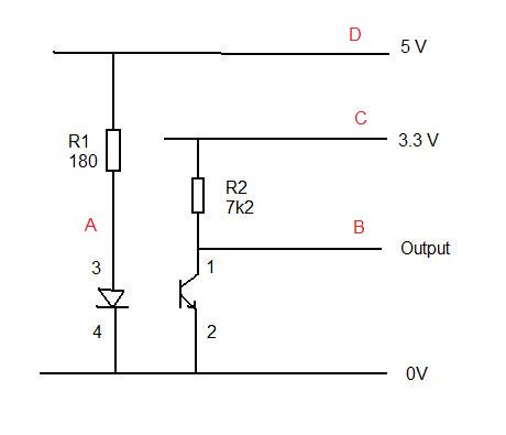
First with the projector turned off and the shutter blades turned away from the IR receiver, measure the voltage at the four points. Now turn the blades so the white painted one is close to the IR receiver at the point where it triggers the mouse and repeat the measurements. What I hope to tell from this is how much current the LED part is drawing and how much current the phototransistor draws when it is turned on. To work out the current I will need to assume the resistor values are as in your marked up version of my circuit above with R1 equal to 180 ohms and R2 equal to 6k2 (6200).
The graphs in the spec sheet for the IR receiver imply it is most sensitive at about 0.02" or about 0.5 mm, which ties up with what you are finding. But it should still operate fine at 0.1" or about 2.5 mm. If you can trigger it with just your hand this sounds good as human skin should not be as reflective as gloss white paint. The spec sheets also say it will trigger in microseconds which is at least 100 times faster than you need even at 18 fps. It may be you need a circuit similar to the one suggested by buckethead to clean up the pulses, but let's see how the voltage measurements come out first.Regards
JamesReuben -
Hi James
This is a temporary set-up, the distance probably 1mm or a bit more (those small lines on the yellow background are millimeters)

These are my readings:
Projector off:
A: 1.29
B: 3.4
C: 3.4
D: 4.2
Projector on:
A: 1.29
B: 2.8; 2.9
C: 3.4
D: 4.2
So the only difference I could detect was with B
Regards
Albiie -
Sorry Albie, I wasn't clear about the second set of measurements. I should have added this was also projector off and stationary blades with the white one next to the sensor. If your second set is with projector stationary, then the phototransistor is definitely not switching on enough. If the blades are moving it is not possible to tell.
What I can tell so far is that the LED is working and drawing about 16 mA. R1 could be reduced in value to increase the current to a maximum value of 50 mA. This will make the LED brighter and therefore more likely to switch the transistor on, but it may also cause it to switch on when you don't want if it gets a bit of reflection from one of the matt black blades for instance. For the moment let's leave this where it is.
The 5 V supply is lower than expected which could indicate a problem with volt drop on the cable (cable to long or too thin). However as the 3.3 V supply is good it doesn't indicate a generic problem here with the cable and this is the more important one for switching.
If it was working as expected B should be around 0.4 V when the projector is off and the white blade is in front. Once you can either confirm this was your measuring condition or repeat the second set in this condition I should be able to suggest the next step.
Just to be sure there are no problems with the cables and to save exchanging another set of messages with my one week delay added, can you also check the voltages where you have connected wires to your mouse as follows. Measure against the same zero volt point you used previously.
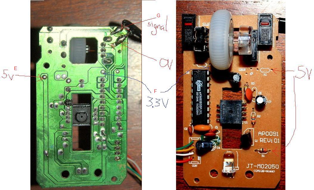
Projector off, blades stationary and turned away from the IR receiver: measure the 5 V (point E), 3.3 V (point F) and signal (point G). This set should be at the same time as the first set.
Projector off, blades stationary and white painted blade in front of the IR receiver: measure the 5 V (point E), 3.3 V (point F) and signal (point G). This set should be at the same time as the second set.
These should be the same or very close in value to B, C and D, but will allow any cable problems to be eliminated.
As a final check on the cables, measure between the zero volt point on the detector circuit and the zero volt point on the mouse. The projector state doesn't matter for this one. This should of course be zero or very close to it.
Don't let these setbacks get to you, you are still close to getting it working. I am impressed how well you are doing with no background in electronics, especially as there is a one week delay between feedback to you. I have also learnt that I need to make it clear what I am saying. I will try to check my email again tonight, but can't guarantee it.Regards
JamesReuben -
Hi James
I'm leaving for the airport right now. Unfortunately I tested with the blades rotating!! Will try only after next week and will post the values then.
These are some of the places that I have posted- might be interesting for you to see their comments.
http://forum.allaboutcircuits.com/showthread.php?t=24107
http://www.dutchforce.com/~eforum/index.php?showtopic=26847
http://www.electro-tech-online.com/electronic-projects-design-ideas-reviews/93594-trig...ect-paint.html
Keep well and thanks
Albie -
Hi James
Here are the results:
With the IR detector facing away from the blade:
A: 1.3V
B: 3.4 V
C: 3.4 V
D: 4.25 V
With the IR detector facing towards the stationary blade:
A: 1.3V
B: 1.55 mV
C: 3.4 V
D: 4.25 V
E: 4.25Projector off, blades stationary and turned away from the IR receiver: measure the 5 V (point E), 3.3 V (point F) and signal (point G).
F: 3.4
G: 3.4
E: 4.25VProjector off, blades stationary and white painted blade in front of the IR receiver: measure the 5 V (point E), 3.3 V (point F) and signal (point G).
F: 3.4V
G: 155mV
0.02mVAs a final check on the cables, measure between the zero volt point on the detector circuit and the zero volt point on the mouse. The projector state doesn't matter for this one. This should of course be zero or very close to it.
So it looks as my point E just produces 4.25V. Should I try a different spot, or is this OK? One can see there is a definite drop in the signal when the sensor is in front of the stationary blade. At least one can also see what happened when the blade was rotating (previous post)
Thanks for your advice
Regards
Albie -
No problem with the 4.25 V since it is the same at D and E, so there is none dropped in the wiring. The only value that stands out is G at 155 mV, which might mean a volt drop on the wire between B and G. However even then it is still low enough to trigger the mouse input which only needs to be below 0.8 V (800 mV). May just need to resolder the connections at either end of this wire.
I looked at the other forums and I think a lot of people have been confusing things. Without a doubt the best feedback you have is from Mr RB on http://www.electro-tech-online.com/electronic-projects-design-ideas-reviews/93594-trig...ect-paint.html. Try his suggestion of replacing R2 with 100 k, or even take it out altogether as there is an internal resistor of 170 k in the mouse.
I would not recommend changing R1, the results you have measured show it is turning the transistor on. I also wouldn't recommend an opto-interrupter for all the same reasons given by Mr RB. As I said before you are really close to getting it working.Regards
JamesReuben -
I need serious help.
With R2 replaced by 100k Ohm
B (Output) Stationary: 3.1V (facing away from white blade)
Facing white blade: 0.07 mV
Moving: 2.4Volt
Does not trigger “Capture” on Cinecap
With R2 replaced by 100kOhm and R1 replaced by 68 Ohm:
B: Stationary: 3.38V (facing away from white blade)
Facing white blade: 0.37 mV
Moving: 1.68Volt
Does not trigger “Capture” on Cinecap
So, I am not sure what I am doing wrong.
I bought this Slotted IR optical switch yesterday (OPB365T), just in case I get stuck: Datasheet:
http://www.digchip.com/datasheets/parts/datasheet/344/OPB365P55.php

Does the beam need to be broken in that first 1mm transparent part, or does the object need to go deeper in the slit?

If so, I can try to mount it close to two movable parts, that move only when a frame advances (so it is stationary and then either move down- that white piece)

Or to the right:

These two possible trigger points are very consistent.
So, should I try this optical switch, I need to know the following
1. How deep should the object need to go in the slit (because if it needs to go deeper, it might be difficult)II thought of attaching a rigid plastic to the "moving" side of one ot the trigger points.
2. What wires should be connected to what pins (For me this is very important, being a newbie to electronics)
3. Do I need resistors?
Some good news- I have managed to set-up my projector/lens/camcorder and get a sharp aerial image.
Once I have sorted my electronics out, what programme did you use to edit? I know Virtualdub. If you used it, what filters did you use? (or am I jumping the gun)
Thanks
Albie -
Taking R1 down to 68 ohms gives you a current of 43 mA which is getting very near the limit for the LED and you risk burning it out. Your first measurement with 100 k for R2 showed you were getting an output down to 0.07 mV which is more than adequate. I strongly recommend you put the 180 resistor back.
Mr RB suggested fitting a trimpot, this may well be the solution because you can then adjust the value of R2. I would put the original 6k2 in series with this so if you wind the trimpot to zero it won't burnout the transistor.
Before doing this I just want to check something. Did you fit a switch which I showed as SW2 in my posting back in my posting on page 4 of this topic dated 10 05 09? Have you tried with this switch (or the original left mouse button in the modified mouse if it's still there) to see if it will trigger Cinecap. I found the modified mouse goes to sleep after a while and needs to be unplugged from the USB and plugged back in again to wake it up.Regards
JamesReuben -
I have used my IR detector and mounted it to the rear trigger.
R1: 68 OHM
R2: 100k (not a trimpot)
Picture of the triggering system- works well, up to now:
The putty didn't com out so neat!

No, I didn't install a switch, but I will see how it goes -
Hi, back again after doing a few more tests. Two things about Cinecap.
I’ve Now had my master files back from Video station. They did a good job of transferring a number of 50 ft reels at 25 fps. I know that projector speeds are not constant, even after warm up, (Dismissing variable speed projectors here for a moment.) it has been my experience that a full 50 ft Super 8 reel should at 18 fps, project a running time of 3 minutes and 20 seconds. 24 fps comes in at about 3 minutes. I stand corrected of course. I find that Cinecap’s default 18 fps is wrong. This is what I found.
I took 1 50 ft reel and converted it on the 601d, I lost no frames. I then took the same film file from Video station and compared the two, they were the same length. I converted the films in Cinecap using the 18 fps. The resulting footage was 2 minutes and 59 seconds long. I know that I may perhaps come across a bit picky here but achieving the correct running speed is important to me. You see, about 20 years ago I had the same footage professionally transferred using the best system available to me at the time. It was done on a variable speed projector at about 16 fps to reduce flicker. This always annoyed me when I compared it to the running speeds of my projectors. Viewing the footage before and after converting in Cinecap only frustrated me more. The good news is that I played around with the settings in Cinecap and found that setting the speed change characteristics to 16/17 or 16/17 fps gives very good results indeed. I wonder if anyone else has noticed this? I just think that there may be many users out there who are blindly converting their footage at the wrong speed, although for most this is an unimportant factor and of course this is all based upon knowing what speed that original footage was shot at too.
The other thing I would like to ask is... I want to do a complete restore on my PC and give it a good clean up Not having saved my Cinecape program before installing it I will loose it. I Have bought the licence and have the key safe etc but where can I find the original trial to download again as I hear that it is no longer available. -
Hi James
Well, I have not, but will do so.Before doing this I just want to check something. Did you fit a switch which I showed as SW2 in my posting back in my posting on page 4 of this topic dated 10 05 09? Have you tried with this switch (or the original left mouse button in the modified mouse if it's still there) to see if it will trigger Cinecap. I found the modified mouse goes to sleep after a while and needs to be unplugged from the USB and plugged back in again to wake it up.
First the good news. My system is working very well and I get a very sharp picture. Camera, lens and projector now "fixed" on a piece of wood.
I started with one film last night, and half way through, the capturing/mouse started triggering erratically. I suppose this is what you call "go to sleep". So it is just a switch to install? After how long do you find it happening? Do you check regularly if it is capturing or do you switch it off and on at regular intervals. Do you stop the projector then?
Now that it works, I will start experimenting with the other resistors. Will need to wait till the weekend to do that. I am concerned about the comments about the one resistor, as you said the current might be too high. Will try with the 180 Ohm again.
Secondly- post processing- what do people use? I used Virtualdub in the past and I am quite familiar with it. If someone is using it, what filters are they using? In the past I sharpened it a bit, used levels to get a proper black and played with the colour. This time I will need to "flip" the image as well.
A huge thank you from me!!
Albie -
I have a stupid question...
is there a recommended or better size for the condenser lens? I looked into purchasing a Plano Convex lens and there is multiple sizes. Thank you -
Wouldn't it be better to remove the video camera lens and project directly onto the ccd sensor? Or would that not work?
-
Glad to hear you got your setup working.Originally Posted by avz10
When I talked about the mouse going to sleep, this is when I took a long time getting all the optical alignment set up. When I finished aligning and went to start capturing I would find the mouse clicks would not register. This is why I added the switch SW2 in parallel with the opto transistor so I could force it to capture a frame without running the film through and end up rewinding. Once I started capturing the mouse would never go to sleep. I have had no problem capturing 400' in one go.
One thing I did in the early days was to stick a label over the original LED on the modified mouse (the one it uses to detect mouse movement). This was so it wouldn't move the cursor on screen if I accidentally knocked it. What I found doing this is that the mouse cursor would drift very slowly, so after a few minutes it came off the button in Cinecap and the capturing would stop. I took the label off and it stopped drifting. It could be that your mouse cursor is gradually drifting off the button, you would have to watch it to see if this is the case. I cannot think of another reason why the capture would become intermittent once you have started.
I use Sony Vegas Movie Studio for editing and to adjust colour balance/brightness. Movie Studio comes with DVD Architect which allows you to create whatever structure you want for your DVD. I tried some other programs a few years ago but found they did not allow me to do everything I wanted . The other programs may have added features since then, but I am happy with Sony. Most of this kind of software allows you to download a trial version with a 14 or 30 day licence. I suggest you download a few and see which you get on with. A lot is down to personal preference and what you want to do with the finished product.
I bought the largest lens I could find at a reasonable price on eBay. Mine is 117 mm diameter.Originally Posted by dblan9
You could remove the camcorder lens but this may be more trouble than it is worth. You will invalidate your guarantee for a start and will allow dust to get onto the CCD. There is a website at http://www.super-8.be/s8_Eindex.htm where he used a CCD but he also added more lenses for focussing.Originally Posted by davealtsonRegards
JamesReuben -
Hi.
I am so intruiged with this idea that I want to build it too. Not that I have so many old films to copy, just the engineer in me
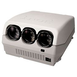
What I need some advice/help with is this plano convex lens. I cannot find one... maybe I am, looking in the wrong places, BUT, I have been offerred an old big lens from one of those old fashioned (modern technology compared to 8mm... but I digress) 3 tube TV projectors.
Will this type of lens do the job? I am not sure if it is a plano convex or not.
Thanks in advance.
Clive
Johannesburg
South Africa -
I don't know about shipping to South Africa, but here is a US link for plano-convex lenses:
http://www.anchoroptics.com/catalog/product.cfm?id=367 -
This is the size of Plano convex lens you require to build a telecine unit.
Plano convex lenses are flat on one side and curved on the other.
Ebay listing...very cheap price for such a big lens.
http://cgi.ebay.co.uk/ws/eBayISAPI.dll?ViewItem&item=220490471584&ssPageName=STRK:MEWA...ht_2374wt_1084 -
I found an old projector lens, from one of these old Sony CRT projectors. I think it will do the trick. (see attached photo).
Its actually got 3 lenses in each one of the 3 tubes, but one of the lenses should do the job fine.
Now to create a light sensor trigger that I hope to mount on the back side of the shutter mechanism....somehow... I will see what plan I need to make once I get to that stage.
thanks for the helpful responses.
Clive
-
Hi!
I have been experimenting with DIY telecine, and stumbled over this thread. Since the original plans for the setup are nowhere to be found, I have a few questions. I am using a Eumig S926GL projector and a Sony EX1 camera. I get pretty decent results filming off a wall. I have no problems with flicker, the variable speed of the projector combined with the ECS shutter system of the EX1 eliminates flicker, so a frame-by-frame setup won't be necessary. But I still have som issues with sharpness and uniformity of image illumination. I'm thinking of buying a plano convex lens and some diffusing material, but is there something else that I need? What is the reason for replacing the bulb with a lower effect one? I am also wondering whether I will be able to telecine negative film with a setup like this? I read somewhere that it's not possible to DIY telecine negative film, but I can't understand why. Any thoughts? -
Hi.
negative film, hmmm, should work, you will have to make it positive on your computer, but it should work. Give it a try and see.
regards
Clive -
OK firstly concerning the low wattage bulb swap...if you use the original 50w/100w bulb and you project your films onto the surface of a plano convex lens you will see nothing...the original high power bulb (needed for projecting a small image onto a wall/screen) is far too bright.Originally Posted by rmossige
Once you swap out the original bulb for a lower wattage bulb you will not be able to project your films onto a screen/wall.
The film image is 'projected' onto the surface of the plano-convex lens and appears to 'float' in the lens...this is what you focus your camcorder on and record.
The instructions for achieving this are all in this (what has become) very long thread
I really don't think you could use this particular DIY unit to telecine negative film stock and achieve acceptable results..you could try and use a computer to reverse the captured images...but I would not hold my breath
This is of course a DIY solution to telecine...you can achieve some fantastic results with patience...the design has its limitations and there are better designs out there for constructing home made telecine machines using machine cameras...eliminating the need for the plano-convex lens... -
For anyone with Mac OSX you can use the free developer tool, Quartz Composer to make your own image capture program. Quartz Composer is included with the Developer Tools installation that comes with the computer. The program itself is programmed like a flowchart and you just connect up the parts you want. One of the nodes is Image Capture and automatically connects to whatever device is connected to the firewire port, you just add a "trigger from the mouse" node and an" export to disk" node and it will capture a single frame (png) whenever the mouse is clicked. You can modify it to do realtime color correction too. (The export to disk node is a free plugin from Apple that you need to add.) It isn't quite as elegant as some of the dedicated programs but it seems to work great and is free.

 Quote
Quote


Similar Threads
-
8mm film to dvd and which video transfer system to use
By krlorenz in forum RestorationReplies: 16Last Post: 28th Jul 2014, 16:12 -
Telecine Home Made Box cheap DIY
By wrathofbod in forum Capturing and VCRReplies: 9Last Post: 1st Feb 2014, 12:30 -
diy telecine - monitoring issues
By TopazUK in forum Capturing and VCRReplies: 0Last Post: 2nd Mar 2012, 14:56 -
Telecine Machine for 8mm film super 8 film transfer to dvd
By igotregister in forum Capturing and VCRReplies: 5Last Post: 2nd Feb 2009, 15:50 -
Trouble playing DVD-Rs on home system
By wysiwyg20 in forum Video ConversionReplies: 1Last Post: 14th Oct 2007, 08:27